The following projects are based on cad. This list shows the latest innovative projects which can be built by students to develop hands-on experience in areas related to/ using cad.

A fuel injector is a device which gives feed for the combustion chamber for the continuously timed combustion. The fuel injector also helps to get the atomization of fuel for the proper combustion, now atomization is nothing but breaking down the liquid state of fuel to very small droplets which helps to get the proper and optimized combustion. Timing of fuel injector is also an important parameter which helps the ic engine to time the process properly hence the RPM at which engine will be running is very high hence the timing of fuel spray inside the chamber is very crucial which again will be in microseconds. Hence the fuel injector should be enough accurate and controllable to work syncing with the other running parts of the engine.

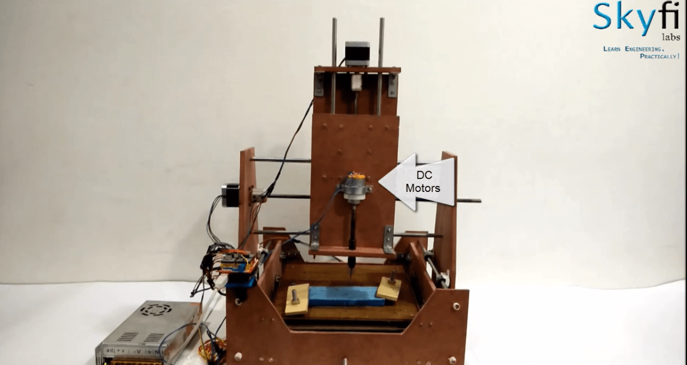
CNC (Computer Numerical Control) machines are used in manufacturing industries to develop a product with more accuracy. CNC machine uses a subtractive method to fabricate or develop a product. In this Arduino project, we are going to develop a miniature CNC machine which can be controlled using Arduino.

Why does science and technology advance so much? Why is it that we put so much effort and money into thinking about, experimenting with, and establishing new theories and principles? The primary reason for the advancements made in science is because, at the end of the day, these advancements help us lead a more comfortable life. Innovation is what led humanity to the top of the food chart, and it is what helps us stay there.

It's been over a century since the opening days of industrialization. From then a variety of machinery using different technologies have taken a considerable amount of space in our factories and industrial units. As we complete the first two decades of the 21st century we are still in the process of revolution when it comes to how machines work. Today we will be looking at such a revolutionary machine that is powered by PLC (Programmable logic controller) making packing more agile and low cost.

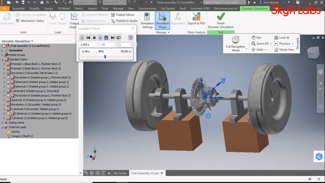
In this CAD project, you will learn to design and simulate a differential gear using Autodesk Inventor software. Autodesk Inventor software is widely used by design engineer professionals to create 2D and 3D models of various parts.
Earlier, manufacturers used to draw the 2D diagram of the product to be designed in different views - front view, side view, and top view. Then, they will start to manufacture and test the model. Here a lot of time is invested in manufacturing and testing. To overcome the above issue designers started using CAD software. CAD stands for Computer-Aided Design which is used to design, test and analyze the model.
Want to develop practical skills on latest technologies? Checkout our latest projects and start learning for free

CAD (Computer Aided Designing) is the process of making a 2D or 3D design of a product using the design software which makes designing and upgrading the product design faster compared to the manual drawing.
In this CAD project, we are going to use Autodesk Inventor software to design a Gear train assembly. Autodesk Inventor is a 3D CAD software that enables the user to design, simulate, visualize and create documentation for a product.

CATIA abbreviates to Computer-Aided Three-dimensional Interactive Application which is best suited for operations like CAD (Computer Aided Designing), CAM (Computer-Aided Manufacturing), PLM and 3D design. In this article, we will make a mechanical design and assembly of universal coupling using CATIA software. While building this project you will be introduced to various concepts of CATIA such as part design, Mechanism design, sheet metal and surface modelling.
Universal coupling or U-Joint or Universal Joint shaft is used to transmit the power through shafts by connecting the shafts in different angles. Which also allows the rear axle to move up and down freely without affecting power transmission. Universal Joints are found in transmission shafts of automobiles, industrial motors, propeller shafts, power transmission shaft of helicopter blades, etc.

Sheet metal is one of the most common raw material used by manufacturing industries to make various components. It is a type of metal which is shaped into various components by cutting, punching, stamping and bending. Sheet metal is known for its durability and easy handling. Using sheet metal you can make low volume prototype and can execute the fabrication more effective for high volume production runs.
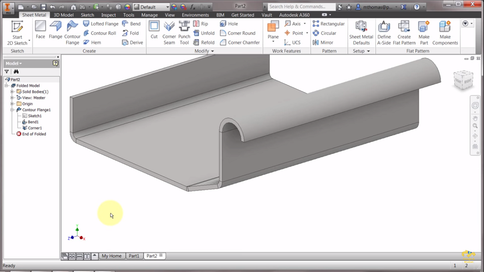
In this CAD project, you will use Autodesk Inventor to create a contour flange using sheet metal design concepts with the help of tools such as line, spline, arc, etc.

Solidworks is a CAD (Computer-Aided Design) and CAE (Computer-Aided Engineering) software used to perform solid modelling. In this article, you will be introduced to various concepts such as part design, mechanism design, sheet metal and surface modelling.

Quantity surveying is a prominent tool used in the construction industry to manage all the costs related to buildings and civil engineering projects. It provides a road map to function the construction processes of a project without any disrupts.
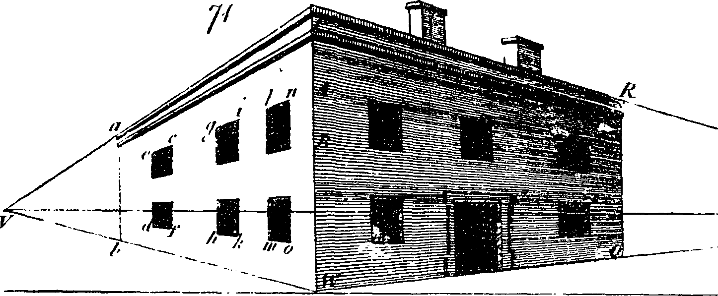
In general, quantity surveying is a combination of estimation and costing of a project. Estimation is a technique of calculating the quantity of the various item of works, such as earthwork excavation, concrete bed, brickwork, masonry, etc. of a structure. Building drawing documents like plan, elevation and section view are generally used for the estimation process. Costing is a process of determining the probable cost that one has to incur to complete the project without any disrupts.

INTRODUCTION:
It portrays a double side shaper machine utilizing a scotch burden system. A Shaper is a machine that is used for forming (metal evacuation) procedures on the workpiece. These days, Industries attempt to accomplish a high creation rate at a negligible measure of time, cost, and so on. The use of a double-side shaper machine wipes out most hindrances looked by a solitary side shaper. The fundamental position of a double-side shaper is that it diminishes time as well as creation cost. In this manner, it expands profitability. A Shaper is a kind of machine apparatus that utilizes direct relative movement between the workpiece and a solitary point cutting device to machine a direct device way. Its slice is comparable to that of a machine. This experiment can be easily carried out in Solidworks.

You can build this project at home. You can build the project using online tutorials developed by experts. 1-1 support in case of any doubts. 100% output guaranteed. Get certificate on completing.
You can build this project at home. You can build the project using online tutorials developed by experts. 1-1 support in case of any doubts. 100% output guaranteed. Get certificate on completing.
Want to develop practical skills on latest technologies? Checkout our latest projects and start learning for free
Join 250,000+ students from 36+ countries & develop practical skills by building projects
Get kits shipped in 24 hours. Build using online tutorials.
Stay up-to-date and build projects on latest technologies