AUTODESK
Sheet metal Contour flange design using Autodesk Inventor
Dineshkumar E

Sheet metal is one of the most common raw material used by manufacturing industries to make various components. It is a type of metal which is shaped into various components by cutting, punching, stamping and bending. Sheet metal is known for its durability and easy handling. Using sheet metal you can make low volume prototype and can execute the fabrication more effective for high volume production runs.
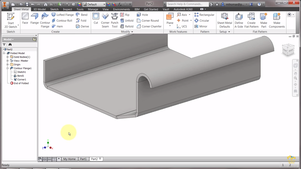
In this CAD project, you will use Autodesk Inventor to create a contour flange using sheet metal design concepts with the help of tools such as line, spline, arc, etc.
Read more..
 Looking to build project on Autodesk Inventor (Career Building Course)?:
Skyfi Labs gives you the easiest way to learn and build this project.
- Autodesk Inventor (Career Building Course) Kit will be shipped to you (anywhere in the world!)
- Use high quality videos to understand concepts and build the project
- Get 1 to 1 expert assistance from Skyfi Labs engineers while doing the project
- Earn a smart certificate on finishing the project
You can start for free and pay only if you like it!
Project Implementation
- Open Autodesk Inventor and click on 2D sketch to start the drawing.
- Use the line tool and draw the shape as per your requirement later the drawing will be extruded to form an appropriate shape. After drawing the sketch mark the dimensions using dimension tab which is present on the taskbar. Then click on finish sketch.
- Now click contour flange option. Using Contour flange you can easily change the offset direction of the sketch and also you can use the thickness of the sketch as centre line to make the offset. Set the required distance in the contour flange and click ok.
- Let’s make the edges proper. For that go-to sheet metal defaults and change the thickness. Now you can observe the thickness is reduced and the shape of the is metal is well-formed.
- Go back to the sketch that you have drawn previously and make some changes in the sketch such as increasing the angle and radius of the semi-circle. Click finish sketch. Now you can observe that the changes are updated in the 3D sketch.
- Now we will implement the same design on a flat plate. Let’s start working on one side of the rectangular flat plate (the long side).
- Start drawing a line perpendicular to the flat plate from the corner followed by another line with an angle and finally one small straight line.
- Use the Contour flange tool and extrude the drawn sketch. Click on the edges to extrude the surface to all the sides except the front. Try making changes in the sketch such as increasing the length or the angle then click on finish sketch. Now, you can observe the changes are updated on the 3D sketch.
Latest projects on AUTODESK
Want to develop practical skills on AUTODESK? Checkout our latest projects and start learning for free
Some more features that you can perform using contour flange:
Specify width extents - using Offset, From To, Width or distance values you can specify the flange width.
- Click more on the contour flange dialogue box.
- On the drop-down list of extents type, you can find the options such as From To, Offset, Width, Distance, etc.
From To - specifies the beginning location of the flange
Offset - to make an offset select a work point of the flange and specify the values.
Distance - modify the distance direction of the sketch relative to the plane as required and specify the distance values.
Multi edge contour flange with Auto-miter
Using Auto-mitering checkbox you can create a Multi edge contour flange. You can find the Auto-mitering option on the corner of the contour flange dialogue box.
 Did you know
Skyfi Labs helps students learn practical skills by building real-world projects.
You can enrol with friends and receive kits at your doorstep
You can learn from experts, build working projects, showcase skills to the world and grab the best jobs.
Get started today!
Kit required to develop Sheet metal Contour flange design using Autodesk Inventor:
Technologies you will learn by working on Sheet metal Contour flange design using Autodesk Inventor:
Sheet metal Contour flange design using Autodesk Inventor
Skyfi Labs
•
Published:
2020-04-10 •
Last Updated:
2022-04-18
 Looking to build project on Autodesk Inventor (Career Building Course)?:
 Did you know